|
|
Once the imager is chosen, the
process for selecting an imaging lens such as popular
M12 or known as s-mount lenses consists of the following
steps:
- Determine the desired field of view (in angles if the object is
at infinity, and in actual sizes if the object is at a finite
distance).
- Calculate the required focal length of the lens, and the image
circle size. We have created a wizard to
perform this calculation.
- Choose an appropriate lens f/# based on similar lighting
environment and depth of field requirement. We have created a
wizard to calculate the depth of field.
- Determine
the appropriate lens performance requirements such as
modulation
transfer function (MTF), chromatic aberration, distortion and
relative illumination.
- Specify the mechanical size constraint and reliability requirements.
Pick the right M12 (S-mount) lens for your project
- Imager format and resolution
- The starting point is the format size which is linked to the effective
area of the imager. The format size definition comes from pre-electronic
imaging era. It does not directly represent the diagonal size of the
effective area. Commonly seen imager formats and their actual physical sizes
are listed below. The imager resolution is the number of effective pixels in
the horizontal and vertical direction. The total number of pixels is often
used to represent the nominal resolution of an imager.
| Imager Format |
Approximate horizontal size (in mm) |
Approximate vertical size (in mm) |
Approximate diagonal
size (in mm) |
| 35mm full frame |
36 |
24 |
43.3 |
| APS-C |
23.6 |
15.6 |
28.3 |
| 1.5" |
18.7 |
14.0 |
23.4 |
| Micro 4/3rd |
17.3 |
13 |
21.7 |
| 1" |
12.8 |
9.6 |
16.0 |
| 1/1.2" |
10.67 |
8 |
13.4 |
| 2/3" |
8.8 |
6.6 |
12.0 |
| 1/1.7" |
8.06 |
4.54 |
9.25 |
| 1/2" |
6.4 |
4.8 |
8.0 |
| 1/2.3" |
6.17 |
4.55 |
7.8 |
| 1/2.5" |
5.7 |
4.32 |
7.2 |
| 1/2.7" |
5.3 |
4 |
6.6 |
| 1/3" |
4.8 |
3.6 |
6.0 |
| 1/3.2" |
4.54 |
3.42 |
5.7 |
| 1/4" |
3.6 |
2.7 |
4.5 |
| 1/5" |
2.56 |
1.92 |
3.2 |
| 1/6" |
2.16 |
1.62 |
2.7 |
Good article
on sensor size trade-offs
- Lens image circle vs. imager size
- The max. image circle of a lens is the area over which the lens will
provide an acceptable performance. For standard applications only lenses
with image circle greater than the imager diagonal size should be selected (download
application note). If the image circle is smaller than the imager
diagonal black or darker corners will result. However, for ultra wide angle
systems, it is common to have the fisheye lens image circle smaller
than the diagonal of the imager. If the entire image circle is contained
within the effective area of the imager, a circular image is formed.
If the imager circle is less than the horizontal width of the imager but
greater than the vertical height, a horizontal frame is formed.
- Effective focal length and field of view
-
Once lens image circle is determined, the next step is
to determine the appropriate lens focal length (EFL) required to achieve the
desired field of view. The lens EFL is an intrinsic property of the lens
independent of the imager used. The max. lens field of view (FOV) is
specified for the image circle size. However, the field of view of CCD/CMOS
camera depends on both the lens EFL and the size of the imager area. If the
lens distortion is small (known as rectilinear lenses), the following
formula can be to calculated the camera FOV:
-
- where x represents the width or height or diagonal size of the imager,
and f is the lens EFL. We have created an online
wizard to perform various FOV/EFL calculation. When there is significant amount of distortion
in the lens such as in the case of very wide-angle lenses and fisheye
lenses, the calculation of the FOV is much more involved. We have developed
a new concept called "rectilinearity" to characterize the distortion
properties of ultra wide-angle and fisheye lenses. When used in
conjunction with the effective focal length, the field of view and
distortion property of a lens can be fully analyzed without having to know
the detailed lens prescription.
- Relative aperture or f/#
- The f/# of the lens has two impacts: (1) amount of light that the lens
collects, and (2) the depth of field (DOF). For low-light
environment, it is often necessary to choose a lens with low f/#.
However the depth of field of a low f/# lens is limited. Low f/#
lenses are also more complex and thus more expensive to produce.
Therefore, the optimal f/#
selection is based on the trade-offs
between various performance parameters and lens cost. It is usually possible to increase the f/#
(stopping down the aperture) of an existing lens design without detrimental
impact on the image quality. However, lowering the f/#
(increasing the
aperture size) is usually not possible without causing significant
compromise in the image quality/relative illumination.
- Nyquist frequency and image quality
- In a digital imaging system the pixel array of the imager samples the
continuous spatial image formed by the optical system. Nyquist Frequency (NF)
represents the highest spatial frequency that the imager is capable of
detecting. The NF depends on the pixel pitch, color filter array (CFA)
design and the processing algorithms of the entire imaging processing chain.
Lens image quality can be the gating factor in the overall image quality of
a digital imaging system. To realize the fully resolution of the imager the
lens resolution should be greater than the NF. The lens should provide sufficient spatial detail
to the imager sensor if each pixel of the imager is to be fully utilized.
Lens image quality is characterized by its modulation
transfer function (MTF). The MTF of a lens varies with spatial
frequency as well as angle of the incidence. A good lens should have MTF >30% up to the sensor Nyquist frequency. It should
also provide a consistent MTF across the entire field of view of the lens.
Simulate impact of MTF to a line pair target.
- Relative illumination and telecentricity
- The light collection ability of all lenses falls off with increasing field
of view. Relative illumination of a lens is defined as the ratio of light
intensity at the maximum angle of view to that on-axis. For electronic imager
sensors (CCD and CMOS), the off-axis brightness is further reduced by
the collection efficiency of imager pixel structure. Many modern imagers use a
micro-lens over each pixel to increase the fill-factor. The micro-lens
will limit the field of view of the pixel. To be maximally compatible
with the micro-lens field of view, the rays emerging from the lens must
be within the acceptance angle of the micro-lens for all off-axis rays. This
typically require that the primary lens be telecentric in imaging spacing.
Non-telecentric lenses can also cause color and resolution cross-talk between
adjacent pixels. This will further impair the off-axis performance of
the imaging system.
Download a white paper on chief ray angle.
- Chromatic aberrations
- Optical materials have different indices of refraction at different
wavelength, known as dispersion. The material dispersion causes light at
different wavelength to focus at different focal plane (axial color) and
different image height (lateral color). Lateral color can be seen as color
fringes at high contrast edges of off-axis objects. Chromatic aberrations can be
minimized or eliminated by using a combination of lens elements with different
dispersion properties. Download a
whitepaper on lateral color.
- Distortion
-
Lens optical distortion describes how the
image is deformed with respect to the object. Distortion (%) is
defined as follows:
where ychief is the image height for an off-axis chief ray, and
yref is a
reference image height for the off-axis field angle. For normal field of view lenses, the reference image height is
defined as:

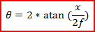
where f is the effective focal length and θ
is the field angle. The resulting distortion is known as "rectilinear"
or "f-tan" distortion.
Most standard photographic lenses have low rectilinear distortion. For
wide-angle and fisheye lenses, the reference image height is typically
chosen as the product of focal length and field angle (in radians):

The resulting distortion
is known as "f-theta" distortion. Please note that a zero f-theta
distortion lens can still look very "distorted" visually. It is
possible to "tailor" distortion in such a way that the off-axis resolution is
enhanced from the standard "f-theta" type. Sunex has developed unique
designs and manufacturing know-hows to provide wide-angle lenses with
tailored
distortion. We also provide Photoshop compatible plug-ins to "de-warp"
images taken with tailored distortion lenses.
Visual impact of various lens distortion (value is calculated for the
corners)
- FOVEA Distortion
- It is possible to create lens designs with tailored distortion profile
based on use case. For example in ADAS or autonomous driving cameras,
it may be desirable to see as far as possible over a narrow range of angle
centered on forward direction while still maintaining a wide field of view.
Such an imaging system is quite analogous to human vision where the best
visual acuity is achieved near the fovea region of the retina. A Fovea
Distortion lens provides more resolution on-axis than off-axis in terms of
pixels per degree in the object space. The following graph shows an example
of the angular resolution vs. field angle of such a lens:
- Relative magnification and off-axis object aspect
ratio
- When an object moves away from on-axis position, its image size and shape
can also change. This phenomenon is more pronounced for wide angle or
fisheye lenses. Relative magnification shows the change in magnification of
an object from on-axis position which is 1. Depending on the lens distortion
characteristics, there can also be a magnification difference between
tangential and sagittal directions. For example, a circular object on-axis
can become smaller and is "squeezed" in one direction when imaged at
off-axis angles. The aspect ratio shows the ratio of relative magnification
in tangential direction to that of sagittal direction. If the aspect ratio
is 1, the shape of the object is kept across the field of view. For example,
a square shaped object is still a square, not a rectangle.
- Rectilinearity
- Lens distortion is characterized by its mapping function.
Well-known discrete mapping functions or projections include:
rectilinear, stereographic, equidistant, equisolid angle and orthographic.
The concept of "rectilinearity" is introduced by Sunex as a
generalized parameter to characterize the entire mapping function set
including these known functions. Please contact
us if you are interested in getting a white paper on rectilinearity.
- Depth of field
or focus
- The depth of field (DOF) of a lens is determined by several factors: the
relative aperture or f/#, the lens EFL, the maximum acceptable blur and the lens
MTF. Generally speaking, higher f/# lenses will have
more DOF. Shorter EFL lenses will also have more DOF. We provide a
wizard to calculate the
depth of field for a given lens. If the MTF of the lens is higher, the
perceived DOF will also be greater. Because the maximum allowed blur size is
somewhat subjective and application dependent, it is strongly
recommended that experimental verification of the DOF to be performed.
- Flare, scattering and ghost images
- Flare is caused by improper engineering of the lens internal structure
such that light rays outside the field of view is "leaked" into the normal
field of view. Scattering is caused by surface roughness of the lens
element that causes an overall reduction in the contrast of the image.
Ghost images are formed when light rays are bounced multiple times inside
lens/sensor structure causing additional "weak" images to be formed near the
primary image. These are all optical "noises" which can cause
degradation to the overall image quality. Careful consideration must be
taken in the design and manufacturing processes to minimize the undesired
optical noises.
- IR cut-off filter
- IR cut-off filtering in the optical chain is required to form accurate color
images. IR cut-off filtering can be accomplished by inserting an
IR-cut off filter in the lens system.
Another option is to apply the IR cut-off coating onto the lens elements
directly.
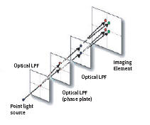
- Optical low-pass filter (OLPF)
- The image formed by a lens is continuous in space. This image is
"sampled" by a CCD/CMOS sensor with a sampling frequency equal to the inverse
of the 2x pixel pitch. If the image contains objects at spatial
frequencies higher than the sampling frequency of the imager, the
resulting image will have aliasing artifacts. This phenomenon is often
observed as colorful fringes (Moire fringes) on the final images. In
high quality imaging systems, optical low-pass filters (OLPF) can be
used to eliminate the Moire fringes. OLPF cuts off the
lens MTF above
the sampling frequency of the imagers resulting an overall MTF that
approximates a step function (in spatial domain). Download an application note on OLPF.
An OLPF is made of 1 to 3 layers of optical birefringent materials such as
quartz. Each birefringent layer splits a light ray by polarization as
shown below:
- Auto-focus (AF) lens
- Auto-focus lenses "track" the object continuously so that the image is
always in-focus regardless of the object movement. This is done by adjusting
the lens (typically using a step motor) to the imager distance based on
measured real-time object distance.
- Zoom lens
- A zoom lens is a lens that has variable effective focal length (EFL).
Since the field of view of a lens is determined by its EFL, a zoom lens
will have variable field of view. When the field of view is decreased,
a "zoom-in" effect is observed. When the field of view of the lens is
increased, a "zoom-out" effect is observed. In "zoom-in" position,
the object detail is magnified but less area of the object is seen. In
"zoom-out" position, more of the object area is observed but detail of
the object is compromised.
|